Auto Changeover Scheme Introduction:
In this post the Auto Changeover Scheme for two incomers and one Bus-coupler system is explained. In Industries for distribution of electrical power with reliable supply this scheme is implemented. This scheme can be find at Distribution level of the plant Single Line Diagram.
Working of Auto Changeover Scheme | Switchgear Panel Boards:
The Load Bus is usually supplied with two incomer feeders to provide redundancy. The bus configuration is generally two bus sections with a bus-coupler breaker normally open.
Each Incomer and the related transformer is connected to one bus section and rated to cater to the full load of both the bus sections.
Auto changeover is provided in these buses to changeover to the healthy bus by closing the bus coupler, should there be any interruption in any of the incoming feeder.
Each Incomer can be closed in two modes.
1. Dead Bus Closing Mode
2. Momentary Paralleling Close Mode
1. Dead Bus Close Mode
In the case of one incomer being under voltage the associated incomer circuit breaker is opened and the bus coupler circuit breaker is closed. In the Dead bus close mode, the CBs are so interlocked that only two CBs shall be ‘ON’ at a time. If two CBs are in closed condition the closing of the third CB shall be prevented ensuring that the supplies are not paralleled at any point of time. This can be achieved through hard wire logic.
Causes for Dead Bus:
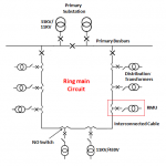
The effect of an electrical fault is manifested by a severe voltage dip. The bus shown in below figure 3.3KV will experience a voltage dip due to any of the faults listed below.
- The incoming feeder and the equipment of the upstream bus ( F1).
- The upstream switchgear busbar (F2).
- Fault in any outgoing feeder of the 11KV and 3.3KV bus (F3).
- Fault in the incomer connecting to the subject 3.3KV bus (F4).
The primary protection is expected to clear the fault that causes the voltage dip within at the most 200 msec. With coordination interval of 300 msec, auto-changeover to healthy bus is initiated after a minimum time delay of 500 msec.

Different Fault Locations Causing Voltage Dip
Significance of Time Delay:
Auto-changeover is initiated by time delayed under voltage signal giving enough time for high speed over current protection to operate first and clear the fault.
The incomer breaker of the affected section has to be tripped first before the bus coupler is closed due to an auto changeover. Otherwise the upstream fault may be fed by the “changed over “healthy source causing it also to trip. It is always “Break before Make” transfer.
2. Momentary Paralleling Close Mode
To return to the normal condition, of both incomer circuit breakers being closed and the bus-coupler circuit breaker being open, or one of the incomers being taken out of service for maintenance, manual momentary paralleling is used. In this case the circuit breaker that is open is closed and one of the remaining two is opened after a delay.
In Momentary paralleling close mode, paralleling of supplies is permitted, subject to certain conditions. Line and Bus synchronization is needed for making Momentary Paralleling. After paralleling of two sources for some time, one breaker is tripped automatically. It is always “Make before Break” transfer.
No-Auto Changeover Case:
In the case of both incomers under voltage, the feeder protection relays detect a system under voltage and neither incomer circuit breaker is opened and the bus coupler circuit breaker remains open.