
2-wire and 3-wire motor control circuits are the basic control circuits encountered in motor control applications. It is important to understand, how to control a magnetic motor starter with a 2-wire control circuit and a 3-wire control circuit.
Before looking into Motor Control Circuits, however, it is necessary to understand the basics of Motor control devices and their symbols used in the ladder diagrams.
Accordingly, The figure below shows several common types of control devices that may be found in a ladder diagram.
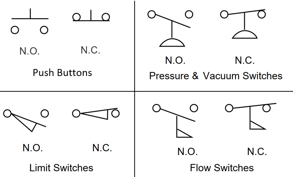
Control Devices Used in Motor Starters:
Normally Open (NO) Switch:
It requires an action to close and complete the circuit. The start push button is NO type.
Normally Closed (NC) Switch:
It requires an action to open the circuit. The stop push button is NC type.
Contactor:
The purpose of the contactor is to pick up and drop off. It uses the Solenoid coil to perform this action.

Contactor also has some auxiliary NO, and NC contacts used for connecting indicating lamps, sequence interlocks, and other pilot circuits.
Solenoid:
A coil of wire that acts as an electromagnet when current passes through it is called a solenoid. It is an electromagnetic switch that connects and disconnects the main supply to the motor.
Holding Contact:
Holding contact is an auxiliary contact that energizes the Solenoid after the start button is released.
A Holding contact is used to disconnect the supply to the motor when the solenoid coil is de-energized in the following two cases.
1. Voltage is low acts as under voltage release
2. Any temporary interruption of power to the solenoid
Thermal Overload Relay (OL):

Thermal Overload Relay made with bimetallic elements with ambient temperature compensator [compensation range- 5oC to 60 oC].
The overload relay protects the motor against overloads and resulting burnouts. We can choose the overload current value from the given range.
2-Wire and 3-Wire Motor Control Circuits:
Control a magnetic motor starter with a 2-wire control circuit:
A 2-wire control circuit is used when a starter is required to function automatically without the attention of an operator.

Refer to the figure below that shows a simple 2-wire control circuit where a pressure switch operates a magnetic motor starter. The main contacts supplying power to the motor are closed when the control system supplies power to a solenoid coil inside the motor starter. The solenoid coil is usually represented by a circle.

When the pressure switch is closed that is normally open, the solenoid coil inside the motor starter got the supply and hence the main contacts supplying power to the motor are closed. And now the motor started.
When the pressure switch is opened due to any reason, then the solenoid coil inside the motor starter cut the supply to the main contacts supplying power to the motor and hence motor stopped.
If a power failure occurs while the contacts of the pressure switch are closed, the starter will drop out. When power is restored, the starter will automatically pick up through the closed contacts of the pressure switch.
In this case, in a 2-wire control circuit, a holding contact in the motor starter is NOT needed.
Unlike a 3-wire control circuit, the motor will start immediately when power is restored to the control circuit. There is no need for an operator to reactivate the control circuit.
Control a magnetic motor starter with a 3-wire control circuit:
A 3-wire control circuit is used to prevent the unexpected starting of motors, which could result in injury to machine operators or damage to the driven machinery.
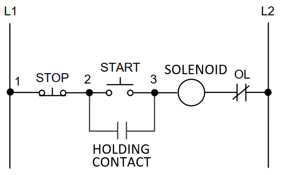
The term “3-wire” control is derived from the fact that in the basic circuit, at least three wires are required to connect the Pressure switch to the starter.

- The stop push button is normally closed (NC). Pushing this button opens the control circuit and cuts power to the solenoid in the motor starter.
- The start push button is normally open (NO) and must be pressed to send power to the solenoid coil.
- The holding contact in the motor starter provides a path around the start push button when it is released.
Any temporary interruption of power to the solenoid opens the holding contact and the motor shuts down. In the case of this 3-wire control circuit, it is necessary for an operator to reactivate the control circuit.
Let us see the practical application of these schemes in direct online starters used for controlling the motor.
Direct Online Motor Starter:
The above-discussed motor control methods are either 2-wire or 3-wire control schemes used in a DOL starter.
Likewise, The figure below gives an idea about these connection types.

In the above figure as shown holding contact is connected for the 3-wire control scheme. And obviously, it is not used for a 2-wire control scheme.
![Core-Balance Current Transformer [CBCT]:](https://electengmaterials.com/wp-content/uploads/2019/04/CBCT-Mounting-Cable-150x150.jpg)
![Under voltage [27]/Over voltage [59] Relay:](https://electengmaterials.com/wp-content/uploads/2019/05/Under-OVer-Voltage-Relay-150x150.jpg)
