
VECTOR or PHASOR GROUPS:
Vector or Phasor groups of transformers are used to denote different connection methods for polyphase transformers. This knowledge is required for connecting the poly-phase transformers in parallel.
To understand the designation of these vector groups one has to know the following assumptions.
- In the phasor diagrams, the phasors rotate in the counterclockwise direction.
- We use the Clock Method of Angle Designation
- According to this method, the HV line phasor is considered as the minute hand always set at the 12 O’clock (zero hours) position, and the corresponding LV line phasor is represented by the hour hand.
- As we know that each digit in the clock differs by an adjacent one with 30°.
- Taking the HV side as the reference (i.e. 12 o Clock position) phase shift of the LV side is mentioned in numerical values in multiples of 30°.
Standard notations used in the Vector groups:
HV Winding:
- Star Y
- Delta D
- Neutral N
- Zig Zag Z
LV Winding:
- Star y
- Delta d
- Neutral n
- Zig Zag z
Vector Groups Classification:
Transformers with similar connections and phase shift are grouped under a Vector group.
In the case of three-phase transformer windings, three forms of connection are possible: “star” (wye), “delta” (mesh), and “interconnected star” (zig-zag). Depending on phase displacement vector groups are classified into the following 4 groups.
Group-1 (0° phase displacement):

• In this connection both HV and LV phasors are in phase with each other.
• In this group Yy0, Dd0 and Dz0 connections are available.
• Here zero denotes both minute and hour hands are in the same position i.e. at 12 O’clock.
• LV phasors are in phase with the HV phasors.
Group-2 (180° phase displacement):

• In this connection both HV and LV phasors are at 180° phase displacement with each other.
• In this group Yy6,Dd6 and Dz6 connections are available.
• Here 6 denotes minute hand is on 12 O’ clock and hour hand is on 6 O’ clock.
• LV phasors lead the HV phasors by 180°.
Group-3 (-30° phase displacement):

• In this connection both HV and LV phasors are at 30° phase displacement with each other.
• In this group Yd1, Dy1 and Yz1 connections are available.
• Here 1 denotes minute hand is at 12 O’ clock and hour hand is at 1 O’ clock.
• LV phasors lag the HV phasors by 30°.
Group-4 (+30° phase displacement):

• In this connection both HV and LV phasors are at 30° phase displacement with each other.
• In this group Yd11, Dy11 and Yz11 connections are available.
• Here 11 denotes minute hand is at 12 O’ clock and hour hand is at 11 O’ clock.
• LV phasors lead the HV phasors by 30°.
Examples of Vector Groups:
The real-time examples for Phasor Groups of transformers are given here. These Phasor Groups can be better understood by the following examples. The Vector diagrams are given in the nameplate details of the transformer
Every Transformer Contains its own Vector Group as shown below figure.
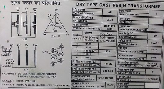
Transformer Name Plate
The following are the mostly used Vector groups of transformers.
Example-1:
As shown in the figure the Vector Group is Dyn11
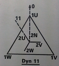
Dyn11 Vector Group
The following information is obtained from the Vector diagram.
- The primary side is Delta denoted by D
- The secondary side is Star with Neutral Connection denoted by yn
- NUMBER (11) denotes phase displacement between HV and LV emfs expressed as clock hour number.
Here Dyn11 represents
A polyphase transformer with HV winding in Delta, LV winding in star with neutral, and the LV line phasor 11 O’clock i.e. 30° ahead of the zero hour position of the HV line phasors.
As shown in the above figure the transformer is having 3 phases on HV Side (1U,1V,1W) and 3 Phases on LV Side (2U,2V,2W).
It means the LV Side U phase Vector 2U leads the HV Side U phase Vector 1U by 30°.
It is applicable to other phases also.
LV Side V phase Vector 2V leads the HV Side V phase Vector 1V by 30°.
LV Side W phase Vector 2W leads the HV Side W phase Vector 1W by 30°.
Example-2:
As shown in the figure the Vector Group is Dyn1
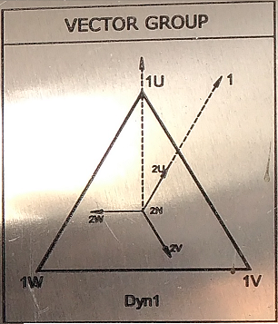
Dyn1 Vector Group
The following information is obtained from the Vector diagram.
- The primary side is Delta denoted by D
- The secondary side is Star with Neutral Connection denoted by yn
- NUMBER (1) denotes phase displacement between HV and LV emfs expressed as clock hour number.
Here Dyn1 represents
A polyphase transformer with HV winding in Delta, LV winding in star with neural, and the LV line phasor 1 O’clock i.e. 30° behind the zero hour position of the HV line phasors.
As shown in the above figure the transformer is having 3 phases on HV Side (1U,1V,1W) and 3 Phases on LV Side (2U,2V,2W).
It means the LV Side U phase Vector 2U lags the HV Side U phase Vector 1U by 30°.
It is applicable to other phases also.
LV Side V phase Vector 2V lags the HV Side V phase Vector 1V by 30°.
LV Side W phase Vector 2W lags the HV Side W phase Vector 1W by 30°.
Example-3:
As shown in the figure the Vector Group is YNd11.
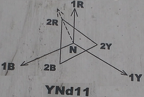
YNd11 Vector Group
The following information is obtained from the Vector diagram.
- The primary side is Star with Neutral Connection denoted by YN
- The secondary side is Delta Connection denoted by d
- NUMBER (11) denotes phase displacement between HV and LV emfs expressed as clock hour number.
Here YNd11 represents
A polyphase transformer with HV winding in Star with neutral, LV winding in delta, and the LV line phasor 11 O’clock i.e. 30° ahead of the zero hour position of the HV line phasors.
As shown in the above figure the transformer is having 3 phases on HV Side (1R,1Y,1B) and 3 Phases on LV Side (2R,2Y,2B).
It means the LV Side R phase Vector 2R leads the HV Side R phase Vector 1R by 30°.
It is applicable to other phases also.
LV Side Y phase Vector 2Y leads the HV Side Y phase Vector 1Y by 30°.
LV Side B phase Vector 2B leads the HV Side B phase Vector 1B by 30°.
Transformer Vector Group Test:
On the nameplate of a three-phase transformer, the vector group is mentioned. Before commissioning the transformer it is necessary to confirm the vector group of the transformer.
For this vector group test is necessary. The procedure for conducting this test is read here.


Thanks electrical commissioning teams