In this post, we are going to see, how the High Impedance Restricted Earth fault protection scheme works by using Metrosil and Stabilizing Resistors.
Why REF protection is required while using a Differential protection scheme?
The Principle of REF protection is the same as Differential Protection.REF Protection is also called Single Phase Differential Protection. The Differential Protection for the transformer can’t cover 100 percent of its winding. As Differential Protection initial setting is usually around 20 percent to avoid CT Errors and all. So if the fault current is below 20 percent it can’t provide protection even for the internal faults.
So we are using REF protection with a lower setting usually around 5 to 10 percent. This Differential Protection provides Protection for 80 percent of the winding and the rest of the protection will be provided by REF.
For non-critical transformers, only Differential protection may be used.
Why REF protection is called Restricted Protection?
It provides protection in the zone between the Transformer Star side winding and it’s Neutral Terminal which is earthed as shown below figure. It senses the fault current only in this particular zone so it is called restricted protection.

How to implement High Impedance Restricted Earth fault protection?
REF protection is implemented using a set of Phase Current Transformers and Neutral Current transformers along with Metrosil and Stabilising Resistors as shown below.

REF WIRING CIRCUIT
REF relay is nothing but an over-current relay that is connected in parallel with the three-phase CTs and one neutral CT.
Working Principle:
The CT secondaries ( phase and neutral CTs) are wired to cancel each other’s currents during external faults and to drive all secondary currents to the relay when the fault is inside the protected zone. (Same as Differential Protection)
High impedance Restricted Earth Fault protection is voltage-based operating protection.
The connections of Metrosil, Stabilizing Resistor, and neural CT are shown in the above figure.
Purpose of Metrosil:
It is a Voltage Limiting Non-Linear Resistor. Non-Linear resistors are connected in parallel with the relay circuit to limit the peak voltage developed across the high-impedance components during internal faults to a safe level below the insulation level of the current transformers, relay, and interconnecting leads.
Purpose of Stabilizing Resistor: RS
The stabilizing resistor is connected in series with the over-current relay and this combination is connected in parallel with the CT branches. It makes sure the relay will not trip during an external fault.

Metrosil and Stabilizing Resistor
Purpose of Neutral CT:

Neutral CT
This is the Class-PS current transformer connected between the Neutral transformer and the earth. Any unbalance current that flows through the neutral of the transformer is sensed by Neutral CT.

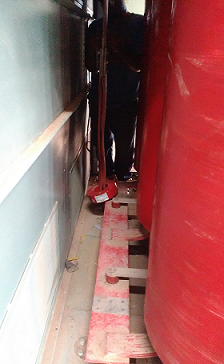
Placing Neutral CT on Transformer Neutral


![Differential Protection Relay [87]:](https://electengmaterials.com/wp-content/uploads/2019/03/differential-relay-150x150.jpg)

do you have a recommendation for the stabilizing resistor? Do you have a manufacturer / resistor series to recommend? I need with the metrosil 1213/R2/600A/S1 a stabilizing resistor 2kOhms 100W/10 sec. but I don’t know which model to purchase.