
Important Electrical Interview Questions:
For preparing for any Electrical job interview knowledge of various technical components is required. we have started a series of Electrical questions to help the interview participants who are looking for jobs in the core sector.
Here we discuss the following basic Electrical interview questions.
- What are the necessary conditions required for the parallel operation of transformers?
- How many times more the Induction motor will be heated during starting than running?
- What is a Capacitive voltage indicator? Where it is used and how it works?
- What are IPBD and SPBD?
- What are the different types of CT testing methods?

1. What are the necessary conditions required for the parallel operation of transformers?
The various conditions that must be fulfilled, for the successful parallel operation of 3-phase transformers, are as follows:
- The line voltage ratios of the transformers must be the same.
- The transformers should have equal per-unit leakage impedances.
- The ratio of equivalent leakage reactance to equivalent resistance should be the same for all the transformers.
- The transformers should have the same polarity.
In addition to these four conditions, two more essential conditions that must be fulfilled for the parallel operation of three-phase transformers are as follows:
Relative-phase displacement:
The relative phase displacement between the secondary line voltages of all the transformers must be zero i.e. the transformers to be connected in parallel, must belong to the same group number.
YY with ΔΔ transformers cannot be connected in parallel.
Note: Transformers of group numbers 3 and 4 can be successfully operated in parallel.
For Vector groups of transformers refer to Vector Groups for 3-phase transformers
Phase sequence:
An improper phase sequence would give unbalanced voltages at the load terminals consequently parallel operation is not possible.
2. How many times more the Induction motor will be heated during starting than running?
An induction motor usually draws six times the full load current for which it is rated when starting. This high stator current induces a comparably high current in the rotor. The rotor resistance at zero speed is three times the rotor resistance when the motor is at rated speed. Thus, the I2r heating in the rotor is approximately 62*3=108 times the I2r heating when the motor runs normally. So the manufacturer has to consider the maximum locked rotor time and locked rotor amps while designing the motor.
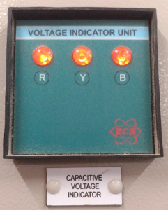
3. What is a Capacitive voltage indicator? Where it is used and how it works?
Capacitive voltage indicators are installed in the panels of medium voltage switchgear for simple voltage checking. Capacitive voltage indicator tells either “voltage present” or “no voltage present” only. If there is potential on the bus bar the LEDs are flashing else no LED flash.
For some applications, there is no need to measure the voltage for connecting further measurements or protective equipment like Voltmeters and Relays. An example likes to detect a system to verify safe isolation from the supply. The voltage-free conditions on the equipment, provide guarantee personal safety during operation and work on the switchgear panel.
If a system is isolated from the supply there should be no voltage present. For such applications, equipping the switchgear panel with Potential Transformers is very expensive.
For such situations, voltage detection using Capacitive voltage indicators offers an efficient and cost-reducing alternative and is ideally suited for medium-voltage switchgear systems.
Principle of operation of capacitive voltage indicators:
Capacitive voltage indicators worked based on capacitive voltage dividers. These consist of capacitors connected in series. The voltage across individual capacitors is divided in inverse proportion to the ratios of their capacitances. The smallest value capacitor is coupled to the bus bar. The largest value capacitor is connected to the LED circuit. If any voltage is present LED flashing occurs otherwise no LED flashing. Like this with the help of Capacitor voltage divider circuits, Capacitive voltage indicators show the presence of voltage on the bus bars.
4.What are IPBD and SPBD?
These are the different bus ducting methods.
IPBD: Isolated Phase Bus Duct
The application is to form an alternator power lead out. The conductors between Generator Transformer, Unit Auxiliary transformer are enclosed in hollow, tubular aluminum enclosures. These enclosures are continuous and are connected in star and earthed at each end. The conductors are supported on porcelain insulators within the enclosure as shown in the below figure.
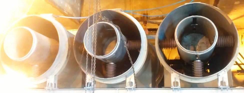
IPBD is used because of its highest reliability and short-circuit resistance. IPBD is preferably used to reduce electrodynamic forces between conductors during short circuit conditions, hence simplifying insulator design.
View the Single Line Diagram of the Power plant for identifying the running path of IPBD.
SPBD: Segregated Phase Bus Duct
The three-phase conductors are inside an enclosure but segregated from each other. SPBD is used to avoid the occurrence of phase-to-phase short circuits. SPBD runs between UAT and Unit Auxiliary Bus and also Station Transformer and Station Bus.

The conductors of the three phases are in common metal enclosures with metal barriers between them as shown in the above figure.
View the Single Line Diagram of the Power plant for identifying the running path of SPBD.
5. What are the different types of CT testing methods?
This is one of the common Electrical questions asked, You should have the knowledge of each test.
- Polarity test
- Winding and Insulation resistance tests
- Ratio test
- Knee point voltage test
Also, go through all the series of Electrical questions for Interviews and give your valuable suggestions to improve further writing.

Very useful sir