
Conducting Polarity test of new three phase Induction motor is necessary before running into operation. If the wrong polarity motor is supplied with three phase supply, the magnetic field distribution within the motor windings become uneven and the output torque becomes pulsating. The motor draws excessive currents leads to damage of the windings.
Suppose we have a new Induction motor without any marking of the leads, then we need to identify its polarity before using it. Usually six terminals from the three phases of an induction motor are available. If their polarity markings (A1, A2; B1, B2; C1, C2) are not known, then these can be found out by a polarity test on the induction motor.
Polarity Test of Induction Motor:
There are two methods to identify the Polarity of three phase Induction motor.
- Finding polarity by Using A.C supply
- Finding Polarity by Using D.C supply
Finding Polarity of Induction Motor-Method I (by A.C):
Equipments required:
- Six terminal Induction motor
- Multimeter or Continuity Tester
- Single phase A.C supply
- A.C Voltmeter
Here is the process explained.
Step 1:
Continuity test to identify each of the winding terminals [AA BB CC]:
We can do this test with the help of Multimeter by checking continuity between any two terminals. If the two terminals belong to same winding a beep will come.
Do this procedure for all and identify terminals, then mark the terminals as AA, BB and CC.
Step 2:
Test to identify polarities [A1A2 B1B2 C1C2]:
Take any two windings randomly and mark the terminals as A1 A2, B1 B2 (this is the assumption) as shown in figure.
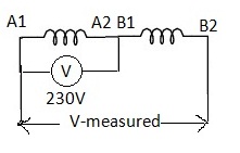
A.C Method of Finding Polarity-01
Now connect A2 with B1 so that the two windings are in series.
Now apply 230V A.C between A1 and A2 and measure the voltage across A1 and B2.
If we notice the measured voltage is less than the applied voltage then our assumption is correct. Otherwise interchange the terminals A1 and A2 and repeat the process so that we can find the terminals A1, A2, B1 and B2.
Now take the third winding mark it as C1, C2 (this is the assumption) and take second winding B1B2 (already known) connect B2 with C1 so that the two windings are in series as shown in fig.
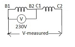
A.C Method of Finding Polarity-02
Now apply 230V A.C between B1 and B2 and measure the voltage across B1 and C2.
If we notice that the measured voltage is less than the applied voltage then our assumption is correct. Otherwise interchange the terminals C1 and C2 and repeat the process so that we can find the terminals B1, B2, C1 and C2.
Once we can identify all the terminals they are connected for Star or Delta fashion, for star connection join A2B2C2 or A1B1C1, for delta connection connect A2B1, B2C1 and A1C2.
Finding Polarity of Induction Motor-Method II (by D.C):
Equipments Required:
- Center – zero galvanometer or milli voltmeter or milli ammeter
- Switch and wires
- Battery (1.5V or 3V)
Procedure to identify terminals A1, A2 and B1, B2:
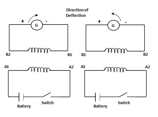
- Randomly choose one of phase winding terminals say A1 and A2.
- Connect the positive terminal of the battery to A1 and the negative terminal to A2 through switch.
- The meter is connected across one of the other two phase windings say B phase randomly.
- At the instant of closing the switch, observe the deflection of the meter pointer.
- If there is a positive or clockwise deflection, then the terminal connected to the positive of meter is B2 and connected the negative terminal is B1.
- If the deflection is in the opposite direction, then the polarities are B1 and B2 respectively.
Procedure to identify other terminals C1, C2:
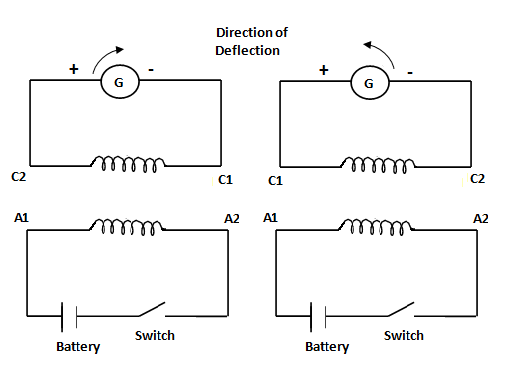
D.C Method of Finding Polarity-02
- Select the first winding with terminals say A1 and A2.
- Connect the positive terminal of the battery to A1 and the negative terminal to A2 through switch.
- The meter is connected across the third phase winding.
- At the instant of closing the switch, observe the deflection of the meter pointer.
- If there is a positive or clockwise deflection, then the terminal connected to the positive of meter is C2 and connected the negative terminal is C1.
- If the deflection is in the opposite direction, then the polarities are C1 and C2 respectively.


How blessed you are my friend, excuse me first let me thank our sustainer & cherisher almighty lord, such a simple and sleek flow like i am having a delicious soup. It fixed me. Thanks & Regards.
Good
very informative and made easy
Thank you for your support and encouragement
Can you help me in solving the three phase sewage induction motor,I do the continuity test line one to line two line two to line three,and it beeps,is it fualty or what.
No induction motors usually Delta connected. If it is Delta connection you will get continuity.
Excellent explained keep it.
Thank You Mr. Ramakant
You forgot the most important step. After inducing voltage/current into secondary windings, ie: B1 – B2, C1 – C2 to establish polarity and marking as “+” or “-” respectively , you must then swap A1 – A2 (your primary) …what was positive supply is now negative. This is on account of “Lenz’s law” where the induced voltage is in opposition to the force that produced it.
Otherwise all else is correct. You can doubt this if you want. Just supply 400VAC and listen for yourself. :o)
What is the reason induction motor too heat while operation and out put efficiency getting low each phase 10 .7 10 .3 and 9.3 amps taking
Hi Satheesh Thanks for asking
Two major reasons that cause overheating of an Induction motor
1. Stator current is a frequently used measurement of load level, but it can easily be masked by an overvoltage condition. A common mistake is made in the practice of operating at an over-voltage to reduce the stator current.
2. Motor operating at inaccurate operational load levels.
Sir galvanometer specifiton pl reply me
Phanibabu
Probably the best explaination I have come across well done ! You should do a YouTube video on this as this part is usually the one that is not explained or omitted.